We often use a Plantronics Voyager 510 Bluetooth headset with our computer, so we can a) listen to streaming video/audio without inflicting our choices nearby innocents, and b) remain untied by a corded headset when we jump up with sudden inspiration.
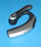
A previous post explored building a USB charger for our cell phone, and we decided to try the same thing to charge our headset. Over time, we are trying to reduce the number of wall-wart chargers used with our laptop, so we don’t have to carry chargers on business trips and to eliminate wasted electricity when the charger is plugged into a wall socket and not charging a gadget. The USB charger for our cell phone used zero standby current, and we hoped to do the same for the headset charger.
USB Standards
A USB port can supply 100mA at 4.75 to 5.25volts. A higher current, to a maximum of 500mA, can be drawn if the port follows a particular handshaking protocol.
|
Pin |
Color |
Name |
|
1 |
Red |
VBus(5V) |
|
2 |
White |
D- |
|
3 |
Green |
D+ |
|
4 |
Black |
Gnd |
Voyager 510 Charging Requirements
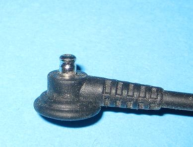
The headset charger has a barrel type plug with diameter 3.0mm and only 3.5mm in length. Notice that the barrel has a reduced diameter region near the end to help the headset “grip” the plug.
The open-circuit voltage measures 5.5V, and the charging current was 63.8mA. This is within the 100mA current limit of USB, and the voltage is close enough to the USB supply voltage that we suspect a direct connection to the VBus and Gnd conductors of a USB cable will successfully keep the headset charged. See the “Design and Experiment” section of a previous article for more in-depth hand-waving.
Construction
Usual Disclaimer: Use this information at your own risk. We are not responsible for damage to your headset or computer.
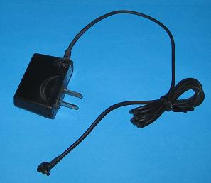
We couldn’t find a similar connector anywhere on Digikey or other electronics parts vendors we searched. (If anyone has found a source, let us know.) Reluctantly we purchased a spare charger on Ebay for less than $5, just to salvage the connector.
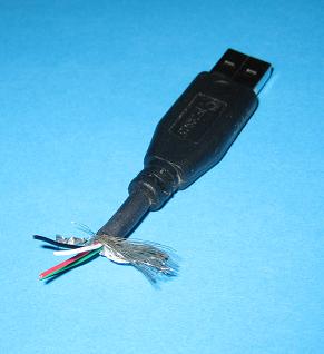
Take a spare USB cord and cut off the series “A” type plug, leaving a few centimeters of cable. Remove a centimeter of outer insulation and shield, exposing four wires. You can cut off the green (D+) and white (D-) wires– they are not needed here.
Cut the spare charger cable 10cm from the connector end, and remove one cm of outer insulation, exposing a red and yellow wire. The red connects to the inner conductor of the plug, 5V, and the yellow connects to outer GND.
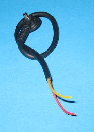
Strip insulation 0.5cm from the wires. Thread a length of shrink-wrap tubing on the cable, and twist the red wires together and solder. Twist the yellow wire from the charger plug to the black wire from the USB plug, and solder.
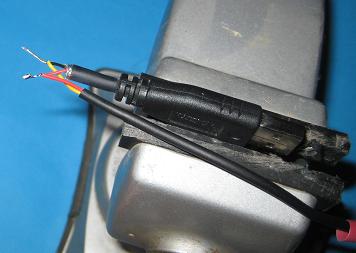
Use a bit of electrician tape to insulate the conductors, and wrap more around both wires for strain relief.
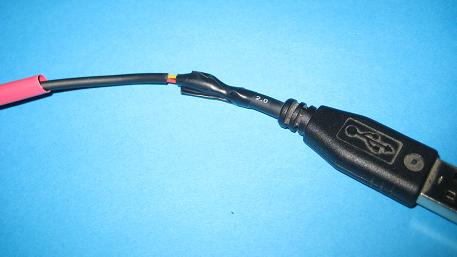
Check continuity with a meter. Slip the shrink wrap tubing over the solder joints and apply gentle heat until snug.
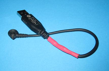
Conclusion
It works!
Related Posts: V176 Cell Phone USB Charger, Power to the Programmers
Thanks – this article was useful to me. Didn’t need the step-by-step, but you confirmed the voltage and current specs of the 510 for me. My situation was that the cats ate the cord – while it was charging the headset – and the short they caused destroyed the charger. So I was left with that weird little botton connector but no working charger to stick a meter on. Anyway, attaching the button connector to a generic 5VDC wall wart works for me…