[This is the third in a series of articles describing installation of a solar hot water system.]
With the panel now securely mounted on the roof, we can turn our attention to plumbing. With an electronics background, I have done plenty of soldering– but only wires, not copper pipe. YouTube has several videos demonstrating the procedure, so it is time to get some pipe and practice “sweating”…
[flash http://www.youtube.com/watch?v=doqoEJJOdYA]
Time to “tool up” for the job:
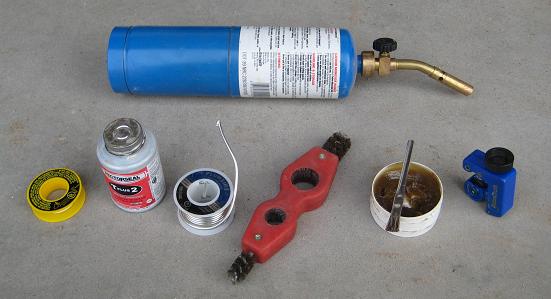
From the top and counter-clockwise: propane torch, teflon tape and pipe dope (more on that below), lead-free solder, 4-in-1 cleaning brush (for removing oxide from 1/2″ and 3/4″ copper tube and fittings), flux with brush, and pipe cutter. Not shown but also recommended are leather work gloves and a bench vise.
We want to avoid as much down-time for hot water availability as possible: teenagers getting ready for school in the morning are not particularly open minded about the advantages of solar energy when they are taking a cold shower. Without disconnecting the current system I could start on the roof and connect the solar panel with pipe near to where the pipe will pass through the roof to turn down towards the storage tank.
Our panel has four connecting ports, two on top and two on bottom. One top port is used for coolant output, and the other can be connected to another panel– not necessary in this installation.
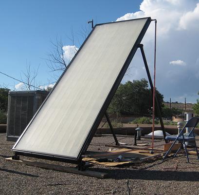
We used the extra top port to connect a pressure relief valve and a coin vent used to purge air bubbles from the coolant loop, which should be installed at the highest point in the system.
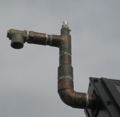
Since the solar panel might someday have to be temporarily removed when our tar and gravel flat roof is redone, we installed unions at the top and bottom ports.
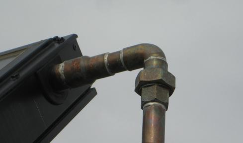
After roof work, I soldered several sub-assemblies of parts together, to make final assembly go faster. Several parts, such as boiler drain valves, pump, and gauges, had pipe threads and required solder-to-pipe adapter fittings.
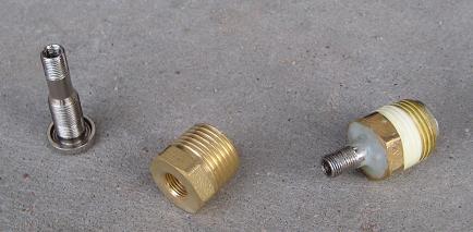
I tested sub-assemblies when possible, using a collection of threaded end-caps and a Schrader valve adapter. I built the adapter using a Schrader valve stem (from an auto parts store), a brass 1/4″ female to 1/2″ male threaded adapter, and a small quantity of JB Weld metal epoxy. The brass adapter is not sized to thread with the valve stem, and relies on epoxy to seal and hold the parts together.
Here is the gadget in action, testing a sub-assembly.
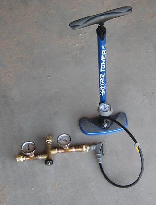
Pressure testing showed no leaks on solder joints, but revealed several leaking threaded joints. Searching the web, we ended up using three layers of yellow (not the thinner white) teflon tape on a male pipe thread, and on top of that brushing on a modest coating of RectorSeal TPlus2 pipe joint compound. Problem solved.
The plan is to remove the old water heater and replace with the solar storage tank on Friday, after the dread teenagers have left for school. My goal is to get cold water back by the end of Friday, finish connecting the coolant loop by end of Saturday, and fill coolant Sunday morning to begin heating water. A professional could work much faster, but I wanted to be methodical, and expected to take breaks to ponder any problems.
Behold our old gas water heater.
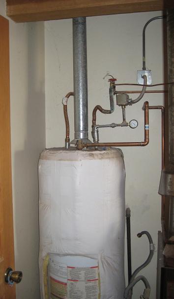
In addition to the hot and cold water connections, you will observe the required pressure relief valve and pipe, as well as some other devices particular to our installation: a pressure limit switch on the cold water line for our water pump, and a valve connecting to 1/4″ copper tubing supplying water to an evaporative cooler. Our new installation will try to “neaten up” this extra hardware.
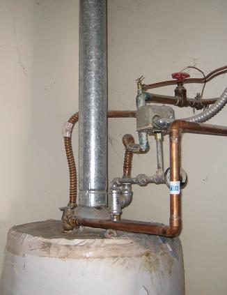
After turning off the gas supply to the water heater, I turn off the water supply, drain any extra water in the lines, unscrew the hot and cold supply to the tank, cut the soldered pressure relief line, and remove the exhaust vent. The hole in the roof for the exhaust vent will make a handy pipe run (passageway) for the coolant loop going to and from the solar panel. After connecting a hose to the tank drain valve, I let the tank empty and moved it out of the way.
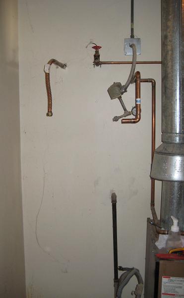
Before putting in the new tank, I attached a plywood mounting panel to studs in the wall with lag bolts. (With hind-sight, I would have mounted the pump-gauges-and-expansion-tank assembly to the panel beforehand, and would mount the panel lower for improved accessibiilty. More on woulda-shouldas in Part 4 of this series.)
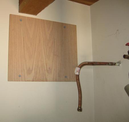
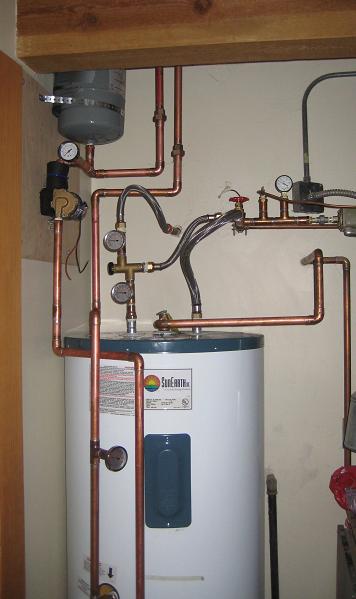
I rolled in the new tank and made connections for hot, cold, pressure relief, and the extra bits mentioned above. All threaded connections used the tape and pipe dope combination mentioned previously. I added a anti-scald mixing valve sub-assembly to prevent scalding in case water in the storage tank got hotter than a normal water heater.
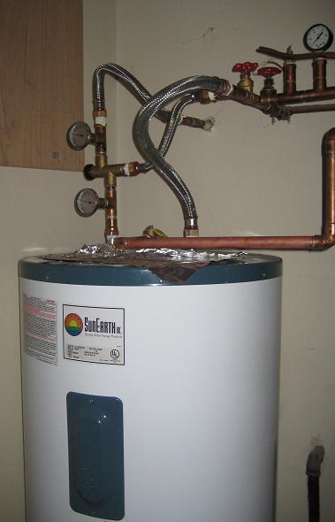
Notice I added thermometers at both the input and output to the mixing valve, which is overkill. The mixing valve requires an extra connection between hot and cold lines, making the connections look more complicated.
See the aluminum foil? I placed that on tank and sometimes walls to shield parts from solder drops and heat.
After turning on water, I was delighted to find no leaks! After a well-deserved break it is time to complete the coolant loop.
I fastened the expansion tank and coolant circulation pump to the mounting board with metal plumber strap, after cushioning between the board and parts with foam rubber to reduce vibration. Unions were used for the pipe runs up to the roof, to make it easier to disconnect for servicing. I thought about adding unions to make it easy to remove the pump– the most likely part to fail after decades of service. Too many unions have aesthetic and reliability issues, so I plan to cut and solder for pump replacement.
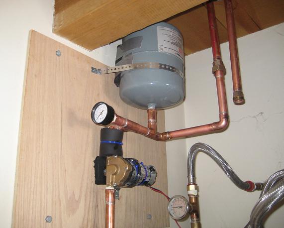
With everything connected in the coolant loop, it is time to pressure test.
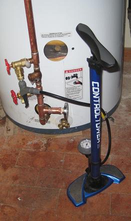
I used a bog-standard bicycle pump with integrated gauge, and pressured up to 10PSI. Sadly, the pressure did not hold, so soap solution was applied to solder joints and threaded joints until a leak was identified:
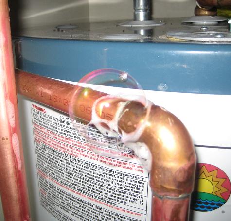
This was one of the last solder connections made, so perhaps I was in too much of a hurry or too complacent. After using wire brush and flux on the pipe and fitting, I did have to let this joint wait for several minutes before sweating. Perhaps this time delay was also a factor. Re-heating and applying more solder did fix the leak.
I pumped the pressure up to 20PSI and discovered another leak that did not leak at 10PSI. This leak would not close with more heat and solder, so I actually had to cut out the leaky fitting and try again with fresh clean parts. Rather than be discouraged, by this time I was getting quite comfortable with cutting pipe and soldering, and glad to be able to take time to do the job right.
After fixing the two leaks, the coolant loop held air at 20PSI for hours with no noticeable loss, so the system is ready to add coolant. I wanted to do that in the morning before the sun is up to begin heating the panel. More on that in Part 4 of this series.